CPR E 281x/282x - Lab 6b
7-
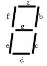
Segment Display in Schematic
1. Objectives
This lab is to review Karnaugh map, logic
function, Sum of Products, and Altera MaxPlus II design graphic editor tools by
implementing a 7-segment display.
1.1 Reference Files for Lab
2. Prelab
Before
you come to lab it will be useful to become familiar with Karnaugh map and
7-segment display. You will find information on Karnaugh and 7-segment display
respectively in section 4.1 and 6.4 of your text: “Fundamentals of Digital Logic with Verilog Design” by Brown and
Vranesic.
3. Setup
As you did in previous labs, make sure you create the
folder in your home directory U:\CPRE281\Lab6b.
4. 7-Segment Display design in
schematics
In this lab, you will implement 7-segment display in schematic
only this time it should display from 0 to F. First, create a truth table for
all the outputs: a, b, c, d, e, f, and g and use Karnaugh map to simplify the
SOPs. On your answer sheet, a template of the truth table and blank K-maps are
provided. Fill out them and derive the simplified SOPs. Try to use
product terms that are common to most outputs. Then draw the schematic for the 7-segment display. Compile and
run the simulator to verify they are correct.
Use the
addition_calc project from the previous lab with your new display decoder, and
observe that now 8+2 = A.
Have the TA to
initial the answer sheet.
7-segment
display from 0 – F:

7-segment
digits: