CPR E 281x/282x - Project Description
Design of a 16-bit Signed Multiplier
1. Objectives
In this project you will implement the algorithm to perform signed multiplication of two 16-bit numbers and calculate a 32-bit result. You will use modules designed in previous labs, combined with control logic, to implement the datapath in this project. The control logic will be implemented in schematic form. You may use either Verilog or schematics for the rest of the datapath.
2.
Signed Multiplier
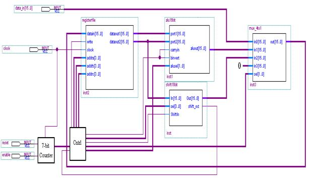
- Create a signed 16-bit multiplier by implementing the datapath shown below, and
- Develop and show the control logic in schematic design format
separately.
Notes:
· You should use the 16x16 registerfile, 16-bit alu, and 16-bit shifter designed in previous labs.
· The Counter should have a 7-bit output, which synchronously counts up on the positive edge of the clock.
· The Cntrl module will provide all the control signals to your modules. Additionally, it will maintain two 1bit registers, F and Shft_out, both of which should be updated on the negative edge of the clock. You should implement the algorithm for signed multiplication using the following steps.
o Step 0 (Initialization):
§ Substep 0: Initialize Multiplicand register à R3 = data_in;
§ Substep 1: Initialize HI register à R1 = 0;
§ Substep 2: Initialize F and Shft_out registers à F= 0; Shft_out = 0;
§ Substep 3: Initialize Multiplier (LO register) à R2 = data_in;
o Steps 1 – 15 (You have to figure out details yourself):
§ Substep 0: Get LSB of Mplier à Shft_out = Mplier[0]; (Obtain using shifter)
§ Substep 1: Add HI and Mcand, store result in HI if Shft_out == 1à if (Shft_out == 1) R1 = R1+R3;
Update
F bit à F = F | (Mcand[15]
& Shft_out);
§ Substep 2: Shift HI register rightà R1[15] = F, R1[14-0] = R1[15-1], Shft_out = R1[0]
§ Substep 3: Shift LO register rightà R2[15] = Shft_out, R2[14-0] = R2[15-1]
o
Step 16
(Correction Step):
§ Substep 0: Get LSB of Mplier à Shft_out = Mplier[0]; (Obtain using shifter);
§ Substep 1: Subtract Mcand from HI, store result in HI if Shft_out == 1à if (Shft_out == 1) R1 = R1 - R3;
§ Substep 2: Arithmetic shift HI register rightà R1[15] = R1[15], R1[14-0] = R1[15-1], Shft_out = R1[0];
§ Substep 3: Shift LO register rightà R2[15] = Shft_out, R2[14-0] = R2[15-1]
o Step 17: Stop
· Each substep above corresponds to 1 clock tick, hence the program will take 68 clock cycles to compute a result.
· To implement the Cntrl module, begin by constructing a table with all outputs, e.g.
|
Counter |
Outputs |
|||
|
addra |
addrb |
addrc |
… |
|
|
0000000 |
|
|
|
|
|
0000001 |
|
|
|
|
|
0000010 |
|
|
|
|
|
… |
|
|
|
|
·
Use the table to
create the assign control outputs based on the counter input. Note:
Although there are 68 substeps, your logic should be
much simpler than that. (Hint: The
two least significant bits of count à substep).
3.
Testing
To test your multiplier, you will have to add outputs
to see the result of the multiplication.
Test for all combinations of signs for multiplier and multiplicand, i.e.
mplier (+) * mcand (+),
mplier (-) * mcand (+),
mplier (+) * mcand (-),
and mplier (-) * mcand (-).
4. Extra
Credit
Using similar blocks, form a different datapath capable of calculating the result in fewer clock
cycles. Hint: It should be possible to
cut the number of cycles required roughly in half.