EABI Guidelines
So, how do the EABI guidelines affect your code? So far, we have been writing assembly language programs without really following any coding rules – just put the instructions together so that the program works correctly. However, as we write more complicated programs, “works correctly” requires that we follow some rules.
One of the main concerns that we have is to use the registers properly. This is especially critical when we have programs that use both C and assembly modules. Remember, the compiler for the C modules is written to follow certain rules, and if we break those rules as assembly language programmers, we can make it impossible for our assembly code to work correctly with the code from the compiler. Register usage is clearly specified in the EABI guidelines:
EABI Register Usage (Table 3 in EABI guidelines)
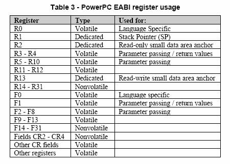
Notice that we recommended registers r3 and r4 for the Read_QTerm and Write_QTerm functions in Lab 7, Section 3, because EABI says that these are to be used for parameter passing and return values.
What other rules are important? Notice the words “volatile” and “nonvolatile.” Volatile means that the register contents need not be preserved by the function; that is, it can change inside a function, so that when the function returns to the caller, it’s okay if the caller sees a different value in that register. Nonvolatile means that the register contents must be preserved by the function; that is, when the function returns to the caller, the caller must see the same value in that register as before it called the function. So, if the function uses the register and changes its value, it must preserve it. Preserving a register means saving its value at the beginning of the function (in the prologue code) and restoring its value at the end of the function (in the epilogue code). A nonvolatile register is sometimes referred to as a “callee save” register, since the callee is required to preserve its value (for the caller).
For example, GPR r11 is volatile. A function can use r11 and is not required to preserve it. Note that r11 was used in the code snippets in Lab 7, Section 2. On the other hand, GPR r31 is a nonvolatile register. So if a function uses r31, it must push r31’s value onto the stack frame. So, you might ask, why would a function use a nonvolatile register to begin with if it requires saving and restoring? Moreover, why does EABI classify most of the GPRs as nonvolatile? (Right, these questions were on the tip of your tongue…) In fact, being nonvolatile is useful. When a function uses a nonvolatile register, it knows that the value of that register will not be changed by any functions that it calls.
When you write assembly code, one of the first steps is to decide which registers will be used by your code. Any nonvolatile registers will then need to be preserved in the prologue (beginning) and epilogue (ending) parts of the function’s code. Actually, the purpose of the prologue and epilogue code is to create and destroy (remove) the function’s stack frame.
EABI Stack Frame
Remember that a stack frame is used to support the call to, execution of, and return from a function. It represents “stuff” that belongs to the function. That stuff includes the return address back to the caller (i.e., the Link Register value), saved GPR register values, local variables, parameters, return value, etc. Some of the stuff is optional. If, for example, GPR registers are used for parameters, return value, and local variables, then the stack frame does not need to allocate space for these items. If the function calls no other functions, then it does not need to save the LR. If the function does not modify any nonvolatile registers, then it does not need space for them on the stack frame either.
Here is a general picture of a stack frame in memory (Figure 2 in EABI guidelines):
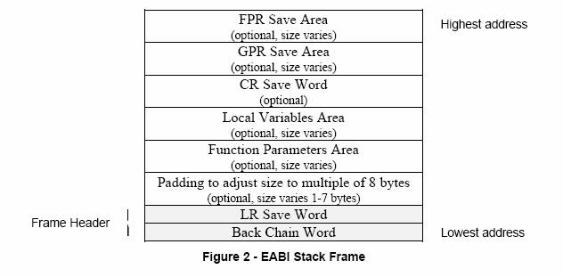
To create this stack frame, the stack pointer (SP) is decremented once for the total space (in bytes) used by the stack frame. EABI specifies that SP points to the last used word on the stack (at the lowest address), that is, to the so-called Back Chain Word of the current stack frame. Then, anything in the stack frame is accessed as a positive offset from SP. Notice that there must be padding in the stack frame so that the total size is double-word aligned (i.e., a multiple of 2 words, or 8 bytes). One subtle detail to note: the LR Save Word that is part of the frame header is actually set aside for a called function to use, not for the current function to save the LR. The current function would be expected to save its LR in the LR Save Word in the previous frame header, i.e., the header of its caller, which is “on top of” the current stack frame. This is illustrated in the next example.
The following example illustrates creation and removal of a stack frame.
Stack Frame Example
Suppose that we are given a main program written in C and two functions written in assembly, as follows:
In main:
Calls function func1
In func1 (assembly):
Uses registers R3, R4, R10, R20, R26-R31
Calls function func2
In func2 (assembly):
Uses registers R3, R11, R15, R28-R31
Calls function msleep
What does the stack look like
after each function call?
Let’s start with an initial runtime
stack that has a stack frame for the main program, shown in yellow below. Only the header is shown.
Higher addresses
|
stack
grows toward lower addresses |
… rest of main’s stack frame |
stack
frame for main |
|
|
||
|
4(SP) |
header (LR Save Word) |
2 frame
header words ß SP |
|
0(SP) |
header (BCW) |
|
|
|
|
|
|
|
|
|
|
|
|
|
|
|
|
|
Lower addresses
Next, when func1 is called, a stack frame is created. What does the stack
frame include?
·
func1 calls function func2, so LR must be preserved (since LR has the return address
back to main).
·
func1 uses registers R3, R4, R10, R20,
R26-R31. Of these, R20 and R26-R31 are nonvolatile and must be preserved.
·
padding
·
frame header
These items are shown in the
stack frame created for func1 below, which is shaded in
green. The following steps are taken to create this stack frame:
1.
Decrement the stack
pointer by the size of the stack frame, in bytes.
§
Count the number of
registers to be saved on the stack. Here, 7.
§
Determine whether any
padding is needed for double-word alignment. Here, since there are 7 words for
saved registers, 1 word of padding is needed for a multiple of 2 words.
§
Add in the frame
header words, i.e., 2 words.
§
Thus, the size of the
stack frame is 10 words, or 40 bytes. Let’s call the size in bytes Z.
2.
Save the current LR in
the LR Save Word in the caller’s stack frame. Here, at (SP)+44. In general, at (SP)+Z+4.
3.
Save the GPR registers
on the stack by storing the register values using indexed addressing relative
to SP.
Higher
addresses
|
stack
grows toward lower addresses |
… rest of main’s stack frame |
stack
frame for main |
|
|
|
|
|
|||
|
44(SP) |
LR for func1 |
ß previous SP |
|
|
|
40(SP) |
header (BCW) |
|
||
|
36(SP) |
r20 |
stack frame
for func1 |
|
|
32(SP) |
r31 |
|
|
|
28(SP) |
r30 |
|
|
|
24(SP) |
r29 |
|
|
|
20(SP) |
r28 |
|
|
|
16(SP) |
r27 |
|
|
|
12(SP) |
r26 |
|
|
|
8(SP) |
padding |
multiple
of 2 words |
|
|
4(SP) |
header |
2 header
words |
|
|
0(SP) |
header |
ß SP |
|
|
|
|
|
|
|
|
|
|
|
|
|
|
|
|
Lower addresses
The following code implements
these steps in the prologue of the function.
func1:
;
function prologue
addi SP,
SP, -40 ; allocate stack frame space
mflr r0 ; get LR (“move from LR” into r0)
stw r0,
44(SP) ; save LR
stw r20,
36(SP) ; save r20
stmw r26,
12(SP) ; save bank of NVs starting with r26
; function body …
This code assumes that SP has been defined using "#define SP r1" in your code.
There is a special instruction
that stores multiple registers into memory, stmw
“Store Multiple Word”, starting with an initial register up through R31. The
operands in the instruction are the initial register and starting address in
memory. So, in this example, the initial register is R26, and the bank of registers R26-R31 are written to memory. The starting address is (SP)+12,
and the registers are stored in consecutive words after that. This is all done
with one instruction. Notice how conveniently this single instruction supports
the saving of nonvolatile registers. The prologue can use it instead of several
stw instructions. Also, this instruction might
explain why EABI has specified a set of registers from R31 on down as
nonvolatile.
The epilogue must remove the
stack frame. It would “undo” the prologue code. The following steps are taken
to remove this stack frame:
1.
Restore the saved GPR
registers from the stack by loading the register values using indexed
addressing relative to SP.
2.
Restore the saved LR
from the LR Save Word at (SP)+Z+4. Here, at (SP)+44.
3.
Increment the stack
pointer by the size of the stack frame, in bytes, i.e., by Z. Here, by 40.
This is the code that would be
executed at the end of the function:
;
function body …
;
function epilogue
lmw r26,
12(SP) ; restore bank of NVs starting with r26
lwz r20,
36(SP) ; restore r20
lwz r0,
44(SP) ; get the saved LR
mtlr r0 ; restore LR (“move to LR” from r0)
addi SP,
SP, 40 ; deallocate
stack frame space
blr ;
exit and return to caller using LR
Notice the use of the special
instruction to load multiple registers from memory, lmw
“Load Multiple Word”, starting with an initial register up through R31.
Next, when func2 is called from func1, another stack frame is
created. What does the stack frame include?
·
func2 calls function msleep, so LR must be preserved (since LR has the return address
back to func1).
·
func2 uses registers R3, R11, R15,
R28-R31. Of these, R15 and R28-R31 are nonvolatile and must be preserved.
·
padding
·
frame header
These items are shown in the
stack frame created for func2 below, which is shaded in
blue. The following steps are taken to create this stack frame:
1.
Decrement the stack
pointer by the size of the stack frame, in bytes.
§
Count the number of
registers to be saved on the stack. Here, 5.
§
Determine whether any
padding is needed for double-word alignment. Here, since there are 5 words for
saved registers, 1 word of padding is needed for a multiple of 2 words.
§
Add in the frame
header words, i.e., 2 words.
§
Thus, the size of the
stack frame is 8 words, or 32 bytes. Let’s call the size in bytes Z.
2.
Save the current LR in
the LR Save Word in the caller’s stack frame. Here, at (SP)+36.
In general, at (SP)+Z+4.
3.
Save the GPR registers
on the stack by storing the register values using indexed addressing relative
to SP.
Higher
addresses
|
stack
grows toward lower addresses |
… rest of main’s stack frame |
stack
frame for main |
|
|
|
|
|
|||
|
|
LR for func1 |
|
|
|
|
|
header (BCW) |
|
||
|
|
r20 |
stack
frame for func1 |
|
|
|
r31 |
|
|
|
|
r30 |
|
|
|
|
r29 |
|
|
|
|
r28 |
|
|
|
|
r27 |
|
|
|
|
r26 |
|
|
|
|
padding |
|
|
|
36(SP) |
LR for func2
|
|
|
|
32(SP) |
header |
ß previous SP |
|
|
28(SP) |
r15 |
stack
frame for func2 |
|
|
24(SP) |
r31 |
|
|
|
20(SP) |
r30 |
|
|
|
16(SP) |
r29 |
|
|
|
12(SP) |
r28 |
|
|
|
8(SP) |
padding |
multiple
of 2 words |
|
|
4(SP) |
header |
2 header
words |
|
|
0(SP) |
header |
ß SP |
|
|
|
|
|
|
|
|
|
|
|
Lower addresses
The following code implements
these steps in the prologue of the function.
func2:
;
function prologue
addi SP,
SP, -32 ; allocate stack frame space
mflr r0 ; get LR (“move from LR” into r0)
stw r0,
36(SP) ; save LR
stw r15,
28(SP) ; save r15
stmw r28,
12(SP) ; save bank of NVs starting with r28
; function body …
The epilogue code would be executed
at the end of the function:
;
function body …
;
function epilogue
lmw r28,
12(SP) ; restore bank of NVs starting with r28
lwz r15,
28(SP) ; restore r15
lwz r0,
36(SP) ; get the saved LR
mtlr r0 ; restore LR (“move to LR” from r0)
addi SP,
SP, 32 ; deallocate
stack frame space
blr ;
exit and return to caller using LR